Network Solution

Network Solution

Success with 802.3bz

- Posted in Network Solution by

In 2016, the IEEE ratified a standard for pushing higher data rates over copper cabling. 802.3bz provides for 2.5 Gbit/S for 300 feet over Cat5e and 5 Gbit/S for 300 feet over Cat6. 802.3bz is available in commercial gear today. Cisco calls it mGig. Aruba calls it Smart Rate, and combines 802.3bz with optional 802.3bt, 60W Power-over-Ethernet.

Access points are really fast, now—particularly with 802.11ax. Even lower-end models are fast enough to outrun a gigabit connection. The problem can be addressed by running two, bonded 1-Gig connections to each AP. With 802.3bz, it may be possible to reuse the existing wiring and push it to 2.5 Gbit/S.

It works! We’ve been deploying a lot of it this past year. But, what about the cost? In order to push 2.5 Gbit/S (or 5 Gbit/S), you will need an access point that supports 802.2bz and a switch port that supports it, too. An 802.3bz deployment will save the cost of one network drop and one switch switch port for each AP, when compared with a bonded, 2 Gbit/S configuration. Assuming the same AP in either case, here are the relative costs:

enter image description here

What this says is that if you’re running two drops and using two switch ports, it will cost you just a little less to use 802.3bz. If you already have an existing network drop going to an access point, then it would be less expensive to run a second drop and consume another switch port. But who wants to do that! What a mess…

  • Kevin Dowd

Spanning Tree Protocol and Broadcast Storm

- Posted in Network Solution by

Problem we are trying to solve: repeat traffic over the same link, particularly broadcast storms. If a layer-2 network has a loop, the same traffic may be forwarded over the same physical network segment repeatedly until its time-to-live expires. Network loops can bring a network down by buying it in traffic.

A collection of switches can be organized into a spanning tree. A spanning tree is a concept from graph theory that describes paths to interconnect all nodes without creating cycles (or loops). So, for instance, nodes A, B,C and D can be interconnected in multiple ways, including:

enter image description here

The topology is a tree. Spanning tree protocols detect cycles (loops) by listening for Bridge Protocol Data Units (BPDUs), which are messages that start at a node designated as the root, and propagate through the tree. When a repeat BPDU is detected, a node makes a calculation about which is the best propagation link among the duplicates. The other, duplicate links are placed into a blocking state. By this mechanism, a spanning tree can be formed among arbitrarily interconnected nodes.

Spanning tree protocols have been used to create resiliency in networks; if one of multiple links goes down, spanning tree protocols may resurrect another. However, multi-path resilience built from link aggregation groups--multiple links cooperating as one--provide combined bandwidth and faster convergence, and are a better design.

Loop detection is a single-switch capability for detecting the interconnection of two or more ports through a another device that doesn't participate in spanning tree. Imagine, for example, two Ethernet ports in a classroom being looped through an unmanaged desktop switch; loop detection will shut down one of the ports.

-Kevin Dowd

Who Ya Gonna Call?

- Posted in Network Solution by

Who ya gonna call?

When there's something bad and it doesn't look good. Who ya gonna call? You contact the manufacturer. Nothing gets resolved. This blog entry is about ten WiFi puzzles we've been invited into over the last year or so. I leave the names out. A few of them aren't even our regular customers.

Case 1: School A, no address disclosed, has a problem with Chromebooks using a shared PSK SSID. Some of the kids can get on. Some can't. All other devices seem to be fine. Diagnosis: the manufacturer's wireless intrusion prevention saw many different devices logging in with the same ID and password and shut them down, thinking that they were massing an attack. Resolution: Disable WIP for this case.

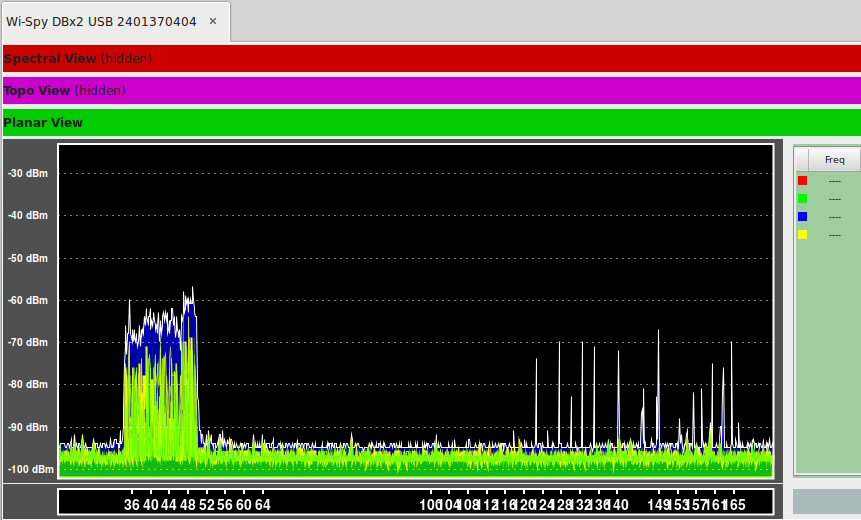
Case 2: School B, no certain address, most kids can't Zoom, can't stream. But some are fine. Diagnosis: school had installed a new LED lighting system over the summer. Non-802.11 communications or noise (makes no difference to the WiFi clients) spiked across the upper part of the 5 GHz spectrum at arbitrary times. Resolution: enable DFS channels and move 5 GHz traffic away from the lighting system.

enter image description here

Case 3: School C, address withheld, can't stream reliably, can't Zoom reliably--all devices affected. Short sessions 'appeared' to be okay. Diagnosis: another vendor had increased the basic WiFi rates and minimum negotiated rates too high. This caused clients to hang onto sessions that were unsustainable and led to high frame loss. Resolution: relax the basic and negotiated rates to make the network useful again. Raising rates is just voodoo, anyway; clients roam when RSSI gets low, not when there's no lower rate choice available.

Case 4: School D, location unknown, WiFi was no good on the second floor. Diagnosis: this was a small school with two floors in a crowded city environment. Resolution: enable band-steering for the 5GHz band and disable 2.4 GHz upstairs.

Case 5: School E, name changed for security, lost WiFi connectivity in some areas of the school every day at the same time. Diagnosis: a manufacturer update had enabled DFS channels. This school was on the glide path to a large airport. One particular 5 GHz channel was re-abandoned every day at the same time as a daily flight came in. Resolution: Disable DFS channels.

Case 6: School F, not the same address as the last one, lost WiFi connectivity every day at the same time. Diagnosis: inspection of AP logs showed that access points lost contact with their controller two or three times a day. Resolution: we found a loop in an MDF that caused a broadcast storm on the wired network. This caused the APs to lose contact with the controller. Not sure why nobody noticed everything else grinding to a halt...

Case 7: School G, address confidential, had 'spinning' WiFi in certain parts of the building. Diagnosis: during a renovation, builders were to remove all of the old access points (and pretty much everything else). They missed a few. When the renovations were complete, and the new switching was installed, the old APs found the controller and began advertising SSIDs. The problem was that these APs weren't supposed to exist, and the networks they were offering weren't trunked to them (these were bridged SSIDs; not tunneled). Students could connect at Layer-2, but that was it. Resolution: shutdown the old APs.

Case 8: School H, address also withheld, had student WiFi that was unable to reach the Internet for some, not all, students. Diagnosis: This was a small school. The wired LAN was bridged to the WiFi network (by design). One day, a teacher had plugged a consumer-grade WiFi router into the wired network. This router began handing out 192.168.0.x DHCP assignments to students as they joined the 10.x WiFi network. Resolution: Unplug the router.

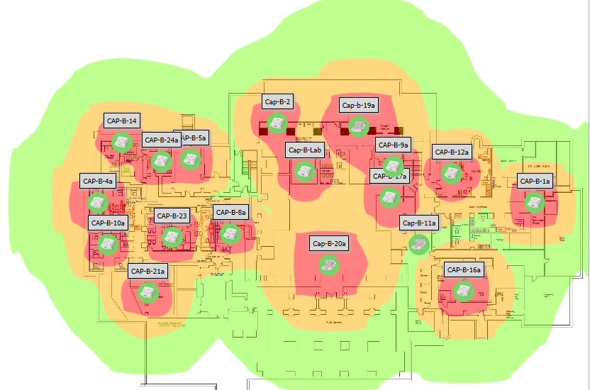
Case 9: School J, address unknown, had bad WiFi in the auditorium. Diagnosis: the auditorium had an impossible number of interfering access points, all with omni-directional antennas. Resolution: shut some of them off and think about partitioning the space with directed coverage for wireless access.

Case 10: School K, wouldn't want me to disclose their address, had "bad WiFi". People "had to reboot," etc. Diagnosis: school had multiple, uncoordinated DHCP servers handing out overlapping network addresses from the same scope. Resolution: Really?! C'mon! Who ya gonna call?

The Death of the Heat Map

- Posted in Network Solution by

The Death of the Heat Map

Fifteen years ago, when organizations were just beginning to experiment with 802.11 wireless networks, the WiFi heat map was considered a good, splotchy plan to show where wireless would be available, and how good it might be. Wifi can travel pretty far under the right conditions. Back then, we built networks for coverage, not necessarily capacity. So any signal was a good signal.

enter image description here

A few years later, we began building WiFi networks for capacity. The object was/is to provide good connections to a community of users across the whole campus. For a good experience, one needs to make an association with an access point that is nearby. Generally, the closer the AP, the better the signal and thus the higher the negotiated data rate. In short: nearby AP good; far-away AP bad.

Consider this, though: if every client is going to be near an AP, then every AP is probably going to be near other APs. That means that there will be overlapped WiFi. Here is an example of what we find in the air is a typical busy campus. This data, in fact, is associated with the heat map above:

enter image description here

The list shows that from the location where the measurement was taken, the client could hear 28 unique access points and 43 radios! Moreover, many of them were on same channels. There were, in fact, so many APs in this space that the amount of bandwidth available for users was being cannibalized by WiFi management frames. This was particularly true in the 2.4 GHz band, where slow beacons transmitted by every radio, every 100 ms could consume the lion’s share of the channel in a kind of death of a thousand cuts. So, in this case, pretty heat map; bad WiFi.

Dense WiFi networking depends on lots of APs running at low power, near their clients. The WiFi infrastructure can play many roles in encouraging clients to choose AP associations wisely. And the latest current WiFi standard, 802.11ax, provides extra features for managing overlapped APs. WiFi has advanced to reach blazing speeds and high densities in the last fifteen years, but the heat map doesn’t tell you much more than it did back then.

  • Kevin Dowd